NXP USA Inc. Distributor -ICONE Electronic
ICONE uses cookies and similar technologies to collect information about you and your interactions and communications with our website and services (including session replays and chat session recordings), which information may be shared with third-party service providers. Please view our Privacy Statement and Cookie Statement for more information. By continuing to use our site, you agree to the terms of our Privacy Statement, the use of cookies, tags, pixels, beacons and other technologies, and our Site Terms and Conditions.
Trustpilot
FIRST SHOPPING ORDER

FIRST ORDER

FREE 10% DISCOUNT

EXCLUSIVE TO NEW CUSTOMERS
banner_page

NXP USA Inc.

Alarms, Buzzers, and Sirens

Results: 110021
Filters
    Stacked Scrolling
  • 110021 Results
  • Img
    Pdf
    Part Number
    Manufacturers
    Desc
    In Stock
    Packing
    Rfq
    74HC166N,652
    Shift Shift Register 1 Element 8 Bit 16-DIP
    6611
    16-DIP (0.300", 7.62mm)
    XPC850SRCZT66BU
    MPC8xx Microprocessor IC MPC8xx 1 Core, 32-Bit 66MHz 256-PBGA (23x23)
    4666
    256-BGA
    MC9S08LH64CLH
    S08 S08 Microcontroller IC 8-Bit 40MHz 64KB (64K x 8) FLASH 64-LQFP (10x10)
    3031
    64-LQFP
    DC6M602X6/1215F,13
    Buck Switching Regulator IC Positive Programmable 1.2V, 1.5V 1 Output 650mA 6-XFBGA, WLCSP
    1961
    6-XFBGA, WLCSP
    M82190G13
    Microprocessor IC *
    1219
    MC07XSF517BEK
    Power Switch/Driver 1:1 N-Channel 5.5A, 11A 54-HSOP
    3008
    54-SSOP (0.295", 7.50mm Width) Exposed Pad
    74LVC1G11GF,132
    AND Gate IC 1 Channel 6-XSON (1x1)
    97
    6-XFDFN
    BZB784-C4V7115
    Zener Diode
    6459
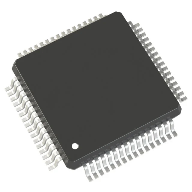
    A Comprehensive Guide To S912XEQ384BVAA Microcontroller IC 16-Bit 50MHz 384KB (384K x 8) FLASH 80-QFP (14x14)

    HCS12X HCS12X Microcontroller IC 16-Bit 50MHz 384KB (384K x 8) FLASH 80-QFP (14x14)


    Introduction

    The MC9S12XE-Family of micro controllers is a further development of the S12XD-Family including

    new features for enhanced system integrity and greater functionality. These new features include a

    Memory Protection Unit (MPU) and Error Correction Code (ECC) on the Flash memory together with

    enhanced EEPROM functionality (EEE), an enhanced XGATE, an Internally filtered, frequency

    modulated Phase Locked Loop (IPLL) and an enhanced ATD. The E-Family extends the S12X product

    range up to 1MB of Flash memory with increased I/O capability in the 208-pin version of the flagship

    MC9S12XE100.

    The MC9S12XE-Family delivers 32-bit performance with all the advantages and efficiencies of a 16 bit

    MCU. It retains the low cost, power consumption, EMC and code-size efficiency advantages currently

    enjoyed by users of Freescale’s existing 16-Bit MC9S12 and S12X MCU families. There is a high level of

    compatibility between the S12XE and S12XD families.

    The MC9S12XE-Family features an enhanced version of the performance-boosting XGATE co-processor

    which is programmable in “C” language and runs at twice the bus frequency of the S12X with an

    instruction set optimized for data movement, logic and bit manipulation instructions and which can service

    any peripheral module on the device. The new enhanced version has improved interrupt handling

    capability and is fully compatible with the existing XGATE module.

    The MC9S12XE-Family is composed of standard on-chip peripherals including up to 64Kbytes of RAM,

    eight asynchronous serial communications interfaces (SCI), three serial peripheral interfaces (SPI), an 8-

    channel IC/OC enhanced capture timer (ECT), two 16-channel, 12-bit analog-to-digital converters, an 8-

    channel pulse-width modulator (PWM), five CAN 2.0 A, B software compatible modules (MSCAN12),

    two inter-IC bus blocks (IIC), an 8-channel 24-bit periodic interrupt timer (PIT) and an 8-channel 16-bit

    standard timer module (TIM).

    The MC9S12XE-Family uses 16-bit wide accesses without wait states for all peripherals and memories.

    The non-multiplexed expanded bus interface available on the 144/208-Pin versions allows an easy

    interface to external memories.

    In addition to the I/O ports available in each module, up to 26 further I/O ports are available with interrupt

    capability allowing Wake-Up from STOP or WAIT modes. The MC9S12XE-Family is available in 208-

    Pin MAPBGA, 144-Pin LQFP, 112-Pin LQFP or 80-Pin QFP options.


    Features

    • 16-Bit CPU12X

    — Upward compatible with MC9S12 instruction set with the exception of five Fuzzy instructions

    (MEM, WAV, WAVR, REV, REVW) which have been removed

    — Enhanced indexed addressing

    — Access to large data segments independent of PPAGE

    • INT (interrupt module)

    — Eight levels of nested interrupts

    — Flexible assignment of interrupt sources to each interrupt level.

    — External non-maskable high priority interrupt (XIRQ)

    — Internal non-maskable high priority Memory Protection Unit interrupt

    — Up to 24 pins on ports J, H and P configurable as rising or falling edge sensitive interrupts

    • EBI (external bus interface)(available in 208-Pin and 144-Pin packages only)

    — Up to four chip select outputs to select 16K, 1M, 2M and up to 4MByte address spaces

    — Each chip select output can be configured to complete transaction on either the time-out of one

    of the two wait state generators or the deassertion of EWAIT signal

    • MMC (module mapping control)

    • DBG (debug module)

    — Monitoring of CPU and/or XGATE busses with tag-type or force-type breakpoint requests

    — 64 x 64-bit circular trace buffer captures change-of-flow or memory access information

    • BDM (background debug mode)

    • MPU (memory protection unit)

    — 8 address regions definable per active program task

    — Address range granularity as low as 8-bytes

    — No write / No execute Protection Attributes

    — Non-maskable interrupt on access violation

    • XGATE

    — Programmable, high performance I/O coprocessor module

    — Transfers data to or from all peripherals and RAM without CPU intervention or CPU wait states

    — Performs logical, shifts, arithmetic, and bit operations on data

    — Can interrupt the HCS12X CPU signalling transfer completion

    — Triggers from any hardware module as well as from the CPU possible

    — Two interrupt levels to service high priority tasks

    — Hardware support for stack pointer initialisation

    • OSC_LCP (oscillator)

    — Low power loop control Pierce oscillator utilizing a 4MHz to 16MHz crystal

    — Good noise immunity

    — Full-swing Pierce option utilizing a 2MHz to 40MHz crystal

    — Transconductance sized for optimum start-up margin for typical crystals

    • IPLL (Internally filtered, frequency modulated phase-locked-loop clock generation)

    — No external components required

    — Configurable option to spread spectrum for reduced EMC radiation (frequency modulation)

    • CRG (clock and reset generation)

    — COP watchdog

    — Real time interrupt

    — Clock monitor

    — Fast wake up from STOP in self clock mode

    • Memory Options

    — 128K, 256k, 384K, 512K, 768K and 1M byte Flash

    — 2K, 4K byte emulated EEPROM

    — 12K, 16K, 24K, 32K, 48K and 64K Byte RAM

    • Flash General Features

    — 64 data bits plus 8 syndrome ECC (Error Correction Code) bits allow single bit failure

    correction and double fault detection

    — Erase sector size 1024 bytes

    — Automated program and erase algorithm

    • D-Flash Features

    — Up to 32 Kbytes of D-Flash memory with 256 byte sectors for user access.

    — Dedicated commands to control access to the D-Flash memory over EEE operation.

    — Single bit fault correction and double bit fault detection within a word during read operations.

    — Automated program and erase algorithm with verify and generation of ECC parity bits.

    — Fast sector erase and word program operation.

    — Ability to program up to four words in a burst sequence

    • Emulated EEPROM Features

    — Automatic EEE file handling using an internal Memory Controller.

    — Automatic transfer of valid EEE data from D-Flash memory to buffer RAM on reset.

    — Ability to monitor the number of outstanding EEE related buffer RAM words left to be

    programmed into D-Flash memory.

    — Ability to disable EEE operation and allow priority access to the D-Flash memory.

    — Ability to cancel all pending EEE operations and allow priority access to the D-Flash memory.

    • Two 16-channel, 12-bit Analog-to-Digital Converters

    — 8/10/12 Bit resolution

    — 3µs, 10-bit single conversion time

    — Left/right, signed/unsigned result data

    — External and internal conversion trigger capability

    — Internal oscillator for conversion in Stop modes

    — Wake from low power modes on analog comparison > or <= match

    • Five MSCAN (1 M bit per second, CAN 2.0 A, B software compatible modules)

    — Five receive and three transmit buffers

    — Flexible identifier filter programmable as 2 x 32 bit, 4 x 16 bit, or 8 x 8 bit

    — Four separate interrupt channels for Rx, Tx, error, and wake-up

    — Low-pass filter wake-up function

    — Loop-back for self-test operation

    • ECT (enhanced capture timer)

    — 8 x 16-bit channels for input capture or output compare

    — 16-bit free-running counter with 8-bit precision prescaler

    — 16-bit modulus down counter with 8-bit precision prescaler

    — Four 8-bit or two 16-bit pulse accumulators

    • TIM (standard timer module)

    — 8 x 16-bit channels for input capture or output compare

    — 16-bit free-running counter with 8-bit precision prescaler

    — 1 x 16-bit pulse accumulator

    • PIT (periodic interrupt timer)

    — Up to eight timers with independent time-out periods

    — Time-out periods selectable between 1 and 224 bus clock cycles

    — Time-out interrupt and peripheral triggers

    • 8 PWM (pulse-width modulator) channels

    — 8 channel x 8-bit or 4 channel x 16-bit Pulse Width Modulator

    — programmable period and duty cycle per channel

    — Center- or left-aligned outputs

    — Programmable clock select logic with a wide range of frequencies

    — Fast emergency shutdown input

    • Three Serial Peripheral Interface Modules (SPI)

    — Configurable for 8 or 16-bit data size

    • Eight Serial Communication Interfaces (SCI)

    — Standard mark/space non-return-to-zero (NRZ) format

    — Selectable IrDA 1.4 return-to-zero-inverted (RZI) format with programmable pulse widths

    • Two Inter-IC bus (IIC) Modules

    — Multi-master operation

    — Software programmable for one of 256 different serial clock frequencies

    — Broadcast mode support

    — 10-bit address support

    • On-Chip Voltage Regulator

    — Two parallel, linear voltage regulators with bandgap reference

    — Low-voltage detect (LVD) with low-voltage interrupt (LVI)

    — Power-on reset (POR) circuit

    — 3.3V and 5V range operation

    — Low-voltage reset (LVR)

    • Low-power wake-up timer (API)

    — Available in all modes including Full Stop Mode

    — Trimmable to +-5% accuracy

    — Time-out periods range from 0.2ms to ~13s with a 0.2ms resolution

    • Input/Output

    — Up to 152 general-purpose input/output (I/O) pins plus 2 input-only pins

    — Hysteresis and configurable pull up/pull down device on all input pins

    — Configurable drive strength on all output pins

    • Package Options

    — 208-pin MAPBGA

    — 144-pin low-profile quad flat-pack (LQFP)

    — 112-pin low-profile quad flat-pack (LQFP)

    — 80-pin quad flat-pack (QFP)

    • 50MHz maximum CPU bus frequency, 100MHz maximum XGATE bus frequency


    NXP Electronics components unboxing,humidity card changed color chip can used?


    7234
    80-QFP
    74HC652DB,112
    Transceiver, Non-Inverting 1 Element 8 Bit per Element 3-State Output 24-SSOP
    1808
    24-SSOP (0.209", 5.30mm Width)
    KMPC850SRVR80BU
    MPC8xx Microprocessor IC MPC8xx 1 Core, 32-Bit 80MHz 256-PBGA (23x23)
    9628
    256-BBGA
    MC9S08SE4MWL
    S08 S08 Microcontroller IC 8-Bit 20MHz 4KB (4K x 8) FLASH 28-SOIC
    3765
    28-SOIC (0.295", 7.50mm Width)
    LD6806TD/21P,125
    Linear Voltage Regulator IC Positive Fixed 1 Output 200mA 5-TSOP
    9838
    SC-74A, SOT-753
    P60D144PAA/9A2410M
    * Microcontroller IC
    2839
    TEA19032BAAT/1J
    USB Controller USB 2.0, USB 3.0 USB Interface 10-SO
    9
    10-SOIC (0.154", 3.90mm Width)
    LPC1115FET48/CP3336
    ARM® Cortex®-M0 LPC1100XL Microcontroller IC 32-Bit Single-Core 50MHz 64KB (64K x 8) FLASH 48-TFBGA (4.5x4.5)
    7548
    48-TFBGA
    MK40DN512ZVMD10
    ARM® Cortex®-M4 Kinetis K40 Microcontroller IC 32-Bit Single-Core 100MHz 512KB (512K x 8) FLASH 144-LBGA (13x13)
    7023
    144-LBGA
    A Comprehensive Guide To S912XDT256F1MAA Microcontroller IC 16-Bit 80MHz 256KB (256K x 8) FLASH 80-QFP (14x14)

    HCS12X HCS12X Microcontroller IC 16-Bit 80MHz 256KB (256K x 8) FLASH 80-QFP (14x14)


    Introduction

    The MC9S12XD family will retain the low cost, power consumption, EMC and code-size efficiency

    advantages currently enjoyed by users of Freescale's existing 16-Bit MC9S12 MCU Family.

    Based around an enhanced S12 core, the MC9S12XD family will deliver 2 to 5 times the performance of

    a 25-MHz S12 whilst retaining a high degree of pin and code compatibility with the S12.

    The MC9S12XD family introduces the performance boosting XGATE module. Using enhanced DMA

    functionality, this parallel processing module offloads the CPU by providing high-speed data processing

    and transfer between peripheral modules, RAM, Flash EEPROM and I/O ports. Providing up to 80 MIPS

    of performance additional to the CPU, the XGATE can access all peripherals, Flash EEPROM and the

    RAM block.

    The MC9S12XD family is composed of standard on-chip peripherals including up to 512 Kbytes of Flash

    EEPROM, 32 Kbytes of RAM, 4 Kbytes of EEPROM, six asynchronous serial communications interfaces

    (SCI), three serial peripheral interfaces (SPI), an 8-channel IC/OC enhanced capture timer, an 8-channel,

    10-bit analog-to-digital converter, a 16-channel, 10-bit analog-to-digital converter, an 8-channel

    pulse-width modulator (PWM), five CAN 2.0 A, B software compatible modules (MSCAN12), two

    inter-IC bus blocks, and a periodic interrupt timer. The MC9S12XD family has full 16-bit data paths

    throughout.

    The non-multiplexed expanded bus interface available on the 144-pin versions allows an easy interface to

    external memories

    The inclusion of a PLL circuit allows power consumption and performance to be adjusted to suit

    operational requirements. System power consumption can be further improved with the new “fast exit from

    stop mode” feature.

    In addition to the I/O ports available in each module, up to 25 further I/O ports are available with interrupt

    capability allowing wake-up from stop or wait mode.

    Family members in 144-pin LQFP will be available with external bus interface and parts in 112-pin LQFP

    or 80-pin QFP package without external bus interface. See Appendix E Derivative Differencesfor package

    options.


    MC9S12XD/B/A Family Features

    • HCS12X Core

    — 16-bit HCS12X CPU

    – Upward compatible with MC9S12 instruction set

    – Interrupt stacking and programmer’s model identical to MC9S12

    – Instruction queue

    – Enhanced indexed addressing

    – Enhanced instruction set

    — EBI (external bus interface)

    — MMC (module mapping control)

    — INT (interrupt controller)

    — DBG (debug module to monitor HCS12X CPU and XGATE bus activity)

    — BDM (background debug mode)

    • XGATE (peripheral coprocessor)

    — Parallel processing module off loads the CPU by providing high-speed data processing and

    transfer

    — Data transfer between Flash EEPROM, RAM, peripheral modules, and I/O ports

    • PIT (periodic interrupt timer)

    — Four timers with independent time-out periods

    — Time-out periods selectable between 1 and 224 bus clock cycles

    • CRG (clock and reset generator)

    — Low noise/low power Pierce oscillator

    — PLL

    — COP watchdog

    — Real time interrupt

    — Clock monitor

    — Fast wake-up from stop mode

    • Port H & Port J with interrupt functionality

    — Digital filtering

    — Programmable rising or falling edge trigger

    • Memory

    — 512, 256 and 128-Kbyte Flash EEPROM

    — 4 and 2-Kbyte EEPROM

    — 32, 16 and 12-Kbyte RAM

    • One 16-channel and one 8-channel ADC (analog-to-digital converter)

    — 10-bit resolution

    — External and internal conversion trigger capabilityFiveFourTwo 1M bit per second,

    CAN 2.0 A, B software compatible modules

    — Five receive and three transmit buffers

    — Flexible identifier filter programmable as 2 x 32 bit, 4 x 16 bit, or 8 x 8 bit

    — Four separate interrupt channels for Rx, Tx, error, and wake-up

    — Low-pass filter wake-up function

    — Loop-back for self-test operation

    • ECT (enhanced capture timer)

    — 16-bit main counter with 7-bit prescaler

    — 8 programmable input capture or output compare channels

    — Four 8-bit or two 16-bit pulse accumulators

    • 8 PWM (pulse-width modulator) channels

    — Programmable period and duty cycle

    — 8-bit 8-channel or 16-bit 4-channel

    — Separate control for each pulse width and duty cycle

    — Center-aligned or left-aligned outputs

    — Programmable clock select logic with a wide range of frequencies

    — Fast emergency shutdown input

    • Serial interfaces

    — SixFourTwo asynchronous serial communication interfaces (SCI) with additional LIN support

    and selectable IrDA 1.4 return-to-zero-inverted (RZI) format with programmable pulse width

    — ThreeTwo Synchronous Serial Peripheral Interfaces (SPI)

    • TwoOne IIC (Inter-IC bus) Modules

    — Compatible with IIC bus standard

    — Multi-master operation

    — Software programmable for one of 256 different serial clock frequencies

    • On-Chip Voltage Regulator

    — Two parallel, linear voltage regulators with bandgap reference

    — Low-voltage detect (LVD) with low-voltage interrupt (LVI)

    — Power-on reset (POR) circuit

    — 3.3-V–5.5-V operation

    — Low-voltage reset (LVR)

    — Ultra low-power wake-up timer

    • 144-pin LQFP, 112-pin LQFP, and 80-pin QFP packages

    — I/O lines with 5-V input and drive capability

    — Input threshold on external bus interface inputs switchable for 3.3-V or 5-V operation

    — 5-V A/D converter inputs

    — Operation at 80 MHz equivalent to 40-MHz bus speed

    • Development support

    — Single-wire background debug™ mode (BDM)

    — Four on-chip hardware breakpoints


    NXP Electronics components unboxing,humidity card changed color chip can used?


    6198
    80-QFP
    74HCT147D,652
    Priority Encoder 1 x 10:4 16-SO
    6871
    16-SOIC (0.154", 3.90mm Width)
    MC33972EWR2
    Switch Monitoring Interface 32-SOIC
    4023
    32-BSSOP (0.295", 7.50mm Width)
    MC9S08SH16CTL
    S08 S08 Microcontroller IC 8-Bit 40MHz 16KB (16K x 8) FLASH 28-TSSOP
    602
    28-TSSOP (0.173", 4.40mm Width)
    LD6815TD/30P,125
    Linear Voltage Regulator IC Positive Fixed 1 Output 150mA 5-TSOP
    6909
    SC-74A, SOT-753
    P60D016PX1C/9B060J
    * Microcontroller IC
    1828
    SPC5744PFK1MLQ5
    e200z4 MPC57xx Microcontroller IC 32-Bit Dual-Core 150MHz 2.5MB (2.5M x 8) FLASH 144-LQFP (20x20)
    2322
    144-LQFP
    S9S12G192F0VLH,557
    12V1 HCS12 Microcontroller IC 16-Bit 25MHz 192KB (192K x 8) FLASH 64-LQFP (10x10)
    7453
    64-LQFP
    PMBT6428,215
    Bipolar (BJT) Transistor
    5724
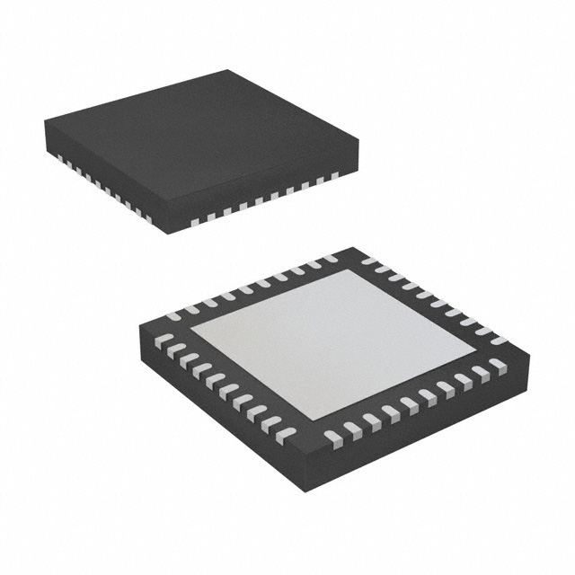
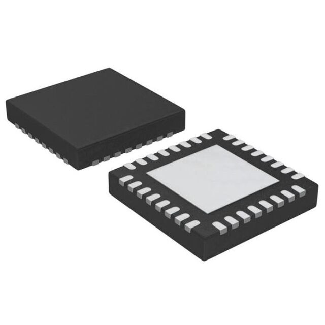
    A Comprehensive Guide To S912ZVL96F0MLFR Microcontroller IC 16-Bit 32MHz 96KB (96K x 8) FLASH 48-LQFP (7x7)

    S12Z S12 MagniV Microcontroller IC 16-Bit 32MHz 96KB (96K x 8) FLASH 48-LQFP (7x7)


    Introduction

    The MC9S12ZVL-Family is an automotive 16-bit microcontroller family using the180nm NVM+UHV

    technology that offers the capability to integrate 40V analog components. This family reuses many

    features from the existing S12 portfolio. The particular differentiating features of this family are the

    enhanced S12Z core and the integration of “high-voltage”analog modules, including the voltage regulator

    (VREG) and a Local Interconnect Network (LIN) physical layer.

    The MC9S12ZVL-Family includes error correction code (ECC) on RAM, FLASH and EEPROM for

    diagnostic or data storage, a fast analog-to-digital converter (ADC) and a frequency modulated phase

    locked loop (IPLL) that improves the EMC performance. The MC9S12ZVL-Family delivers an optimized

    solution with the integration of several key system components into a single device, optimizing system

    architecture and achieving significant space savings. TheMC9S12ZVL-Family delivers all the advantages

    and efficiencies of a 16-bit MCU while retaining the low cost, power consumption, EMC, and code-size

    efficieney advantages currently enjoyed by users of existing S12 families. The MC9S12ZVL-Family is

    available in 48-pin, 32-pin LQFP and 32-pin QFN-EP. In addition to the I/O ports available in each

    module, further I/O ports are available with interrupt capability allowing wake-up from stop or wait

    modes.

    The MC9S12ZVL-Family is a general-purpose family of devices suitable for a wide range of applications.

    The MC9S12ZVL-Family is targeted at generic automotive applications requiring LIN connectivity.

    Typical examples of these applications include switch panels and body endpoints for sensors.


    Chip-Level Features

    On-chip modules available within the family include the following features:

    ·S12Z CPU core

    ·128, 96, 64, 32, 16 or 8 KB on-chip flash with ECC

    ·2048,1024,128 byte EEPROM with ECC

    ·8192,4096, 1024 or 512 byte on-chip SRAM with ECC

    ·Phase locked loop (IPLL) frequency multiplier with internal filter

    ·1 MHz internal RC oscillator with +/-1.3% accuracy over rated temperature range

    ·4-20MHz amplitude controlled pierce oscillator

    ·Internal COP (watchdog) module

    ·analog-to-digital converter (ADC) with 10-bit or 12-bit resolution and up to 10 channels available

    on external pins and Vbg (bandgap) result reference

    ·PGA module with two input channels

    ·One 8-bit 5V digital-to-analog converter (DAC)

    ·One analog comparators (ACMP) with rail-to-rail inputs

    ·MSCAN(1Mbit/s, CAN2.0 A, B software compatible) module

    ·One serial peripheral interface (SPI) module

    ·One serial communication interface (SCI) module with interface to internal LIN physical layer

    transceiver (with RX connected to a timer channel for frequency calibration purposes, if desired)

    ·Up to one additional SCI (not connected to LIN physical layer)

    ·One on-chip LIN physical layer transceiver fully compliant with the LIN 2.2 standard

    ·6-channel timer module (TIM0) with input capture/output compare

    ·2-channel timer module (TIM1) with input capture/output compare

    ·Inter-IC (IIC) module

    ·8-channel Pulse Width Modulation module (PWM)

    ·On-chip voltage regulator (VREG) for regulation of input supply and all internal voltages

    ·Autonomous periodic interrupt (API), supports cyclic wakeup from Stop mode

    ·Pins to support 25mA drive strength to VSSX

    ·Pin to support 20mA drive strength from VDDX (EVDD)

    ·High Voltage Input (HVI)

    ·Supply voltage sense with low battery warning

    ·On-chip temperature sensor, temperature value can be measured with ADC or can generate a high

    temperature warning

    · Up to 23 pins can be used as keyboard wake-up interrupt (KWI)


    7261
    48-LQFP
    74HCT4067N,112
    1 Circuit IC Switch 16:1 120Ohm 24-DIP
    5240
    24-DIP (0.600", 15.24mm)
    MC908MR8CPE
    HC08 HC08 Microcontroller IC 8-Bit 8MHz 8KB (8K x 8) FLASH 28-PDIP
    5398
    28-DIP (0.600", 15.24mm)
    MC9S08SH32MTG
    S08 S08 Microcontroller IC 8-Bit 40MHz 32KB (32K x 8) FLASH 16-TSSOP
    4437
    16-TSSOP (0.173", 4.40mm Width)

    Please send RFQ , we will respond immediately.

    Product:

    *Contact Name

    * Telephone

    Business Email

    * Company Name

    * Country

    * Quantity