FIRST ORDER
FREE 10% DISCOUNT
Img
|
Pdf
|
Part Number
|
Manufacturers
|
Desc
|
In Stock
|
Packing
|
Rfq
|
||||||||||||||||||||||
---|---|---|---|---|---|---|---|---|---|---|---|---|---|---|---|---|---|---|---|---|---|---|---|---|---|---|---|---|---|
Linear Voltage Regulator IC Positive Fixed 1 Output 300mA 4-WLCSP (0.76x0.76)
|
8848
|
4-XFBGA, WLCSP
|
|
||||||||||||||||||||||||||
USB Controller USB Interface 12-X2QFN (1.6x1.6)
|
14
|
12-XFQFN
|
|
||||||||||||||||||||||||||
RF Mosfet 65 V 1.8MHz ~ 470MHz 24dB 1800W OM-1230G-4L
|
30
|
OM-1230G-4L
|
|
||||||||||||||||||||||||||
Bipolar Motor Driver CMOS SPI 28-HVQFN (6x6)
|
1799
|
28-VQFN Exposed Pad
|
|
||||||||||||||||||||||||||
NOW NEXPERIA PMDPB70XPE - SMALL
|
6529
|
|
|||||||||||||||||||||||||||
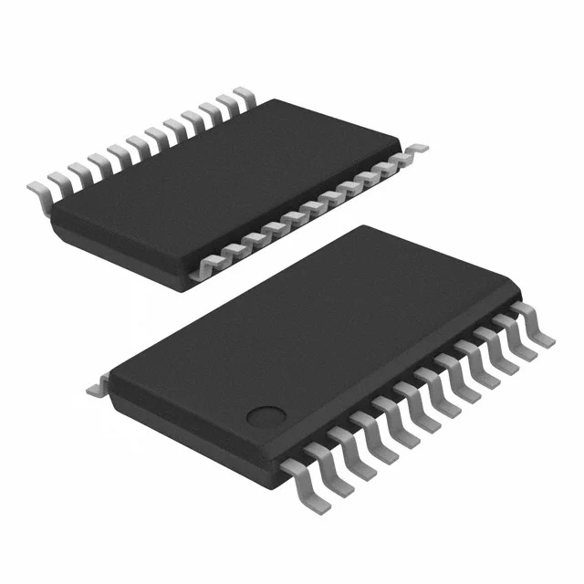
HCS12X HCS12X Microcontroller IC 16-Bit 80MHz 512KB (512K x 8) FLASH 144-LQFP (20x20) MC9S12XDP512 Covers S12XD, S12XB & S12XA Families Introduction The MC9S12XD family will retain the low cost, power consumption, EMC and code-size efficiency advantages currently enjoyed by users of Freescale's existing 16-Bit MC9S12 MCU Family. Based around an enhanced S12 core, the MC9S12XD family will deliver 2 to 5 times the performance of a 25-MHz S12 whilst retaining a high degree of pin and code compatibility with the S12. The MC9S12XD family introduces the performance boosting XGATE module. Using enhanced DMA functionality, this parallel processing module offloads the CPU by providing high-speed data processing and transfer between peripheral modules, RAM, Flash EEPROM and I/O ports. Providing up to 80 MIPS of performance additional to the CPU, the XGATE can access all peripherals, Flash EEPROM and the RAM block. The MC9S12XD family is composed of standard on-chip peripherals including up to 512 Kbytes of Flash EEPROM, 32 Kbytes of RAM, 4 Kbytes of EEPROM, six asynchronous serial communications interfaces (SCI), three serial peripheral interfaces (SPI), an 8-channel IC/OC enhanced capture timer, an 8-channel, 10-bit analog-to-digital converter, a 16-channel, 10-bit analog-to-digital converter, an 8-channel pulse-width modulator (PWM), five CAN 2.0 A, B software compatible modules (MSCAN12), two inter-IC bus blocks, and a periodic interrupt timer. The MC9S12XD family has full 16-bit data paths throughout. The non-multiplexed expanded bus interface available on the 144-pin versions allows an easy interface to external memories The inclusion of a PLL circuit allows power consumption and performance to be adjusted to suit operational requirements. System power consumption can be further improved with the new “fast exit from stop mode” feature. In addition to the I/O ports available in each module, up to 25 further I/O ports are available with interrupt capability allowing wake-up from stop or wait mode. Family members in 144-pin LQFP will be available with external bus interface and parts in 112-pin LQFP or 80-pin QFP package without external bus interface. See Appendix E Derivative Differencesfor package options. MC9S12XD/B/A Family Features • HCS12X Core — 16-bit HCS12X CPU – Upward compatible with MC9S12 instruction set – Interrupt stacking and programmer’s model identical to MC9S12 – Instruction queue – Enhanced indexed addressing – Enhanced instruction set — EBI (external bus interface) — MMC (module mapping control) — INT (interrupt controller) — DBG (debug module to monitor HCS12X CPU and XGATE bus activity) — BDM (background debug mode) • XGATE (peripheral coprocessor) — Parallel processing module off loads the CPU by providing high-speed data processing and transfer — Data transfer between Flash EEPROM, RAM, peripheral modules, and I/O ports • PIT (periodic interrupt timer) — Four timers with independent time-out periods — Time-out periods selectable between 1 and 224 bus clock cycles • CRG (clock and reset generator) — Low noise/low power Pierce oscillator — PLL — COP watchdog — Real time interrupt — Clock monitor — Fast wake-up from stop mode • Port H & Port J with interrupt functionality — Digital filtering — Programmable rising or falling edge trigger • Memory — 512, 256 and 128-Kbyte Flash EEPROM — 4 and 2-Kbyte EEPROM — 32, 16 and 12-Kbyte RAM • One 16-channel and one 8-channel ADC (analog-to-digital converter) — 10-bit resolution — External and internal conversion trigger capabilityFiveFourTwo 1M bit per second, CAN 2.0 A, B software compatible modules — Five receive and three transmit buffers — Flexible identifier filter programmable as 2 x 32 bit, 4 x 16 bit, or 8 x 8 bit — Four separate interrupt channels for Rx, Tx, error, and wake-up — Low-pass filter wake-up function — Loop-back for self-test operation • ECT (enhanced capture timer) — 16-bit main counter with 7-bit prescaler — 8 programmable input capture or output compare channels — Four 8-bit or two 16-bit pulse accumulators • 8 PWM (pulse-width modulator) channels — Programmable period and duty cycle — 8-bit 8-channel or 16-bit 4-channel — Separate control for each pulse width and duty cycle — Center-aligned or left-aligned outputs — Programmable clock select logic with a wide range of frequencies — Fast emergency shutdown input • Serial interfaces — SixFourTwo asynchronous serial communication interfaces (SCI) with additional LIN support and selectable IrDA 1.4 return-to-zero-inverted (RZI) format with programmable pulse width — ThreeTwo Synchronous Serial Peripheral Interfaces (SPI) • TwoOne IIC (Inter-IC bus) Modules — Compatible with IIC bus standard — Multi-master operation — Software programmable for one of 256 different serial clock frequencies • On-Chip Voltage Regulator — Two parallel, linear voltage regulators with bandgap reference — Low-voltage detect (LVD) with low-voltage interrupt (LVI) — Power-on reset (POR) circuit — 3.3-V–5.5-V operation — Low-voltage reset (LVR) — Ultra low-power wake-up timer • 144-pin LQFP, 112-pin LQFP, and 80-pin QFP packages — I/O lines with 5-V input and drive capability — Input threshold on external bus interface inputs switchable for 3.3-V or 5-V operation — 5-V A/D converter inputs — Operation at 80 MHz equivalent to 40-MHz bus speed • Development support — Single-wire background debug™ mode (BDM) — Four on-chip hardware breakpoints NXP Electronics components unboxing,humidity card changed color chip can used? |
4408
|
144-LQFP
|
|
||||||||||||||||||||||||||
EC000 Microprocessor IC M680x0 1 Core, 32-Bit 10MHz 64-QFP (14x14)
|
8969
|
64-QFP
|
|
||||||||||||||||||||||||||
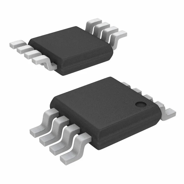
MPC8xx Microprocessor IC MPC8xx 1 Core, 32-Bit 50MHz 357-PBGA (25x25)
|
2631
|
357-BBGA
|
|
||||||||||||||||||||||||||
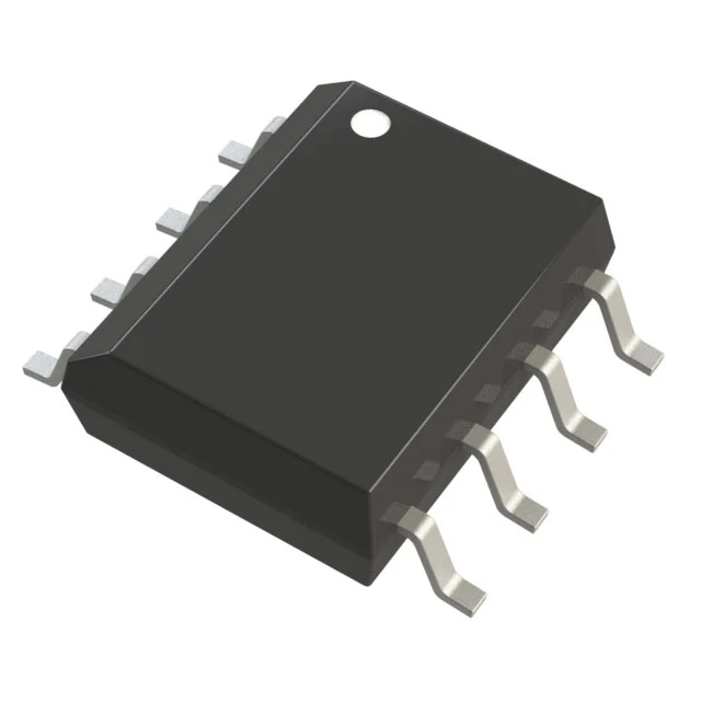
PowerPC e300c3 Microprocessor IC MPC83xx 1 Core, 32-Bit 400MHz 620-HBGA (29x29)
|
7851
|
620-BBGA Exposed Pad
|
|
||||||||||||||||||||||||||
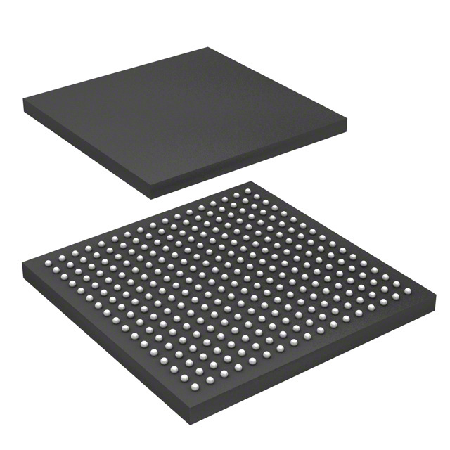
Linear Voltage Regulator IC Positive Fixed 1 Output 300mA 5-TSOP
|
8280
|
SC-74A, SOT-753
|
|
||||||||||||||||||||||||||
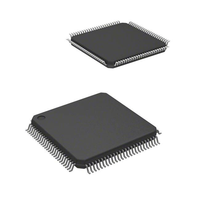
Transceiver CANbus 14-HVSON (3x4.5)
|
5
|
14-VDFN Exposed Pad
|
|
||||||||||||||||||||||||||
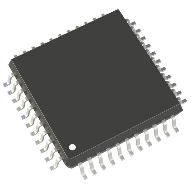
12V1 HCS12 Microcontroller IC 16-Bit 25MHz 64KB (64K x 8) FLASH 32-LQFP (7x7)
|
6341
|
32-LQFP
|
|
||||||||||||||||||||||||||
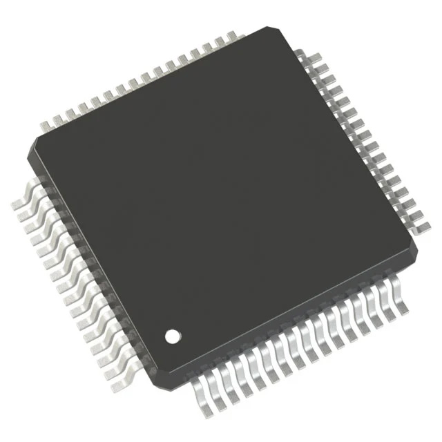
N-Channel 55 V 35A (Tc) 85W (Tc) Through Hole TO-220AB
|
9
|
TO-220-3
|
|
||||||||||||||||||||||||||
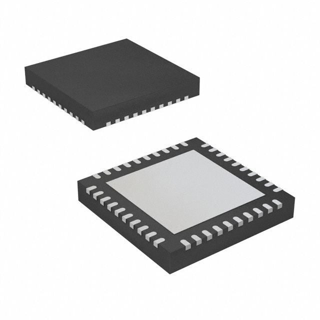
HCS12 HCS12 Microcontroller IC 16-Bit 25MHz 128KB (128K x 8) FLASH 112-LQFP (20x20)
|
2877
|
112-LQFP
|
|
||||||||||||||||||||||||||
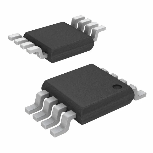
S12Z S12 MagniV Microcontroller IC 16-Bit 32MHz 96KB (96K x 8) FLASH 48-LQFP (7x7) Introduction The MC9S12ZVC-Family is a new member of the S12 MagniV product line integrating a battery level (12V) voltage regulator, supply voltage monitoring, high voltage inputs and a CAN physical interface. It's primarily targeting at CAN nodes like sensors, switch panels or small actuators. It offers various low-power modes and wakeup management to address state of the art power consumption requirements. Some members of the MC9S12ZVC-Family are also offered for high temperature applications requiring AEC-Q100 Grade 0 (-40℃ to +150C ambient operating temperature range). The MC9S12ZVC-Family is based on the enhanced performance, linear address space S12Z core and delivers an optimized solution with the integration of severalkey system components into a single device, optimizing system architecture and achieving significant space savings. Chip-Level Features •On-chip modules available within the family include the following features: •S12Z CPU core •Up to 192 Kbyte on-chip flash with ECC •Up to 2 Kbyte EEPROM with ECC •Up to 12Kbyte on-chip SRAM with ECC •Phase locked loop (IPLL) frequency multiplier with internal filter •1 MHz internalRC oscillator with +/-1.3% accuracy over rated temperature range •4-20MHz amplitude controlled pierce oscillator •Internal COP (watchdog) module •Analog-to-digital converter (ADC) with 12-bit resolution and up to 16 channels available on external pins •Two analog comparators (ACMP) with rail-to-rail inputs •One 8-bit 5V digital-to-analog converter (DAC) •Up to two serial peripheral interface (SPI) modules •Up to two serial communication interface (SCI) modules •SENT Transmitter Interface •MSCAN (1 Mbit/s, CAN 2.0 A, B software compatible) module •One on-chip CAN physicallayer module •8-channel timer module (TIM0) with input capture/output compare •4-channel timer module (TIM1) with input capture/output compare (fast max 64MHz) •Inter-IC (IIC) module •4-channel 16-bit Pulse Width Modulation module (PWM0) •4-channe1 16-bit Pulse Width Modulation module (PWM1) (fast max 64MHz) •On-chip voltage regulator (VREG) for regulation of input supply and all interal voltages •Autonomous periodic interrupt (API), supports cyclic wakeup from Stop mode •Four pins to support 25 mA drive strength to VSSX •One pin to support 20 mA drive strength from VDDX (EVDD) •Two High Voltage Input (HVI) pins •Supply Vsup monitoring with warning •On-chip temperature sensor, temperature value can be measured with ADC or can generate a high temperature interrupt |
7533
|
48-LQFP
|
|
||||||||||||||||||||||||||
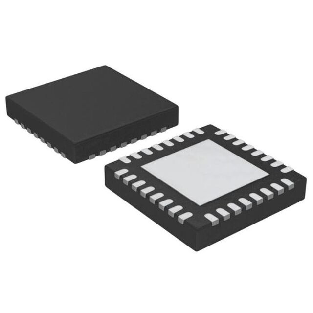
HC08 HC08 Microcontroller IC 8-Bit 8.4MHz 60KB (60K x 8) FLASH 64-QFP (14x14)
|
6329
|
64-QFP
|
|
||||||||||||||||||||||||||
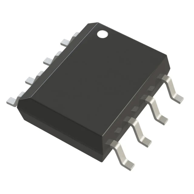
MPC8xx Microprocessor IC MPC8xx 1 Core, 32-Bit 50MHz 357-PBGA (25x25)
|
3756
|
357-BBGA
|
|
||||||||||||||||||||||||||
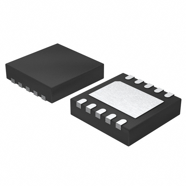
PowerPC e300c4s Microprocessor IC MPC83xx 1 Core, 32-Bit 667MHz 689-TEPBGA II (31x31)
|
1023
|
689-BBGA Exposed Pad
|
|
||||||||||||||||||||||||||
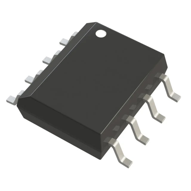
ARM® Cortex®-M0 LPC1100L Microcontroller IC 32-Bit Single-Core 50MHz 32KB (32K x 8) FLASH 28-TSSOP
|
21
|
28-TSSOP (0.173", 4.40mm Width)
|
|
||||||||||||||||||||||||||
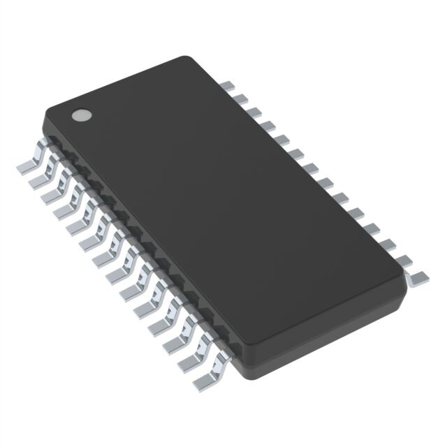
Voltage Level Translator Bidirectional 1 Circuit 1 Channel 100Mbps 6-TSSOP
|
3167
|
6-TSSOP, SC-88, SOT-363
|
|
||||||||||||||||||||||||||
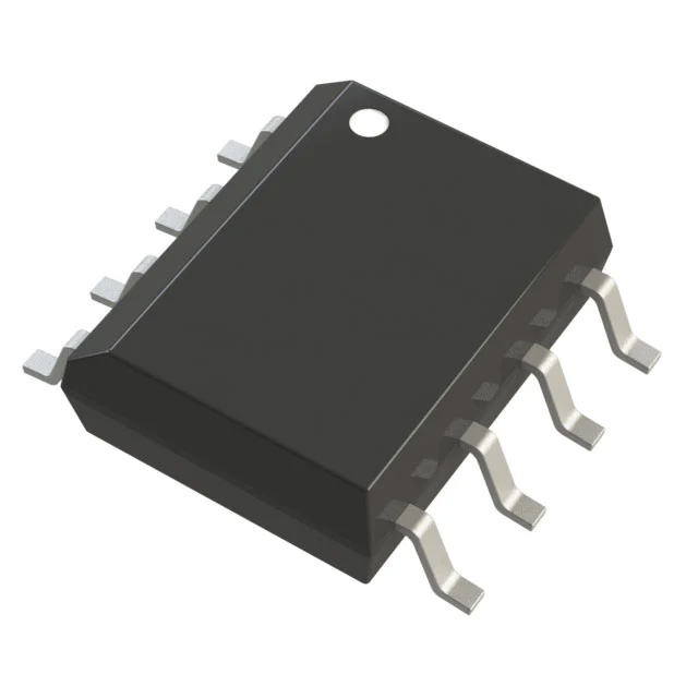
12V1 HCS12 Microcontroller IC 16-Bit 25MHz 48KB (48K x 8) FLASH 64-LQFP (10x10)
|
1969
|
64-LQFP
|
|
||||||||||||||||||||||||||
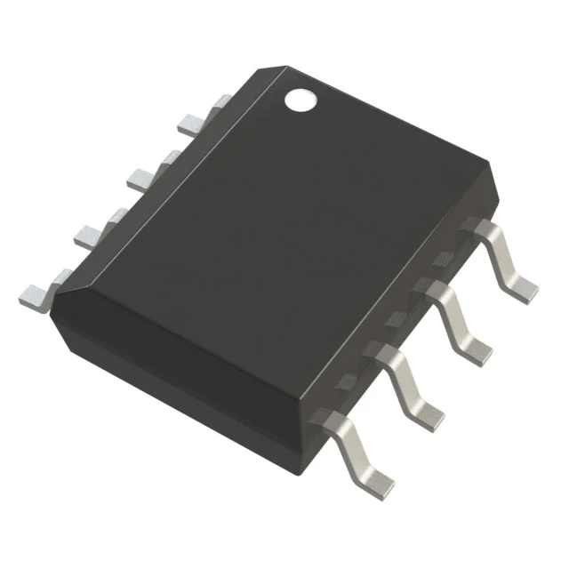
Zener Diode 3.6 V 320 mW ±5% Surface Mount SOD-323
|
1328
|
SC-76, SOD-323
|
|
||||||||||||||||||||||||||
D-Type, Addressable 1 Channel 1:8 IC Standard 16-SO
|
8481
|
16-SOIC (0.154", 3.90mm Width)
|
|
||||||||||||||||||||||||||
XA XA Microcontroller IC 16-Bit 32MHz 32KB (32K x 8) OTP 44-LQFP (10x10) GENERAL DESCRIPTION The XA–C3 is a member of the Philips XA (eXtended Architecture) family of high–performance 16–bit single–chip microcontrollers. The XA–C3 combines an array of standard peripherals together with a PeliCAN CAN 2.0B engine and unique ”Message Management” hardware to provide integrated support for most CAN Transport Layer (CTL) protocols such as DeviceNet, CANopen and OSEK. For additional details, refer to the XA-C3 Overview on page 35. The XA architecture supports: •Easy 16-bit migration from the 80C51 architecture. •16–bit fully static CPU with 24–bit addressed PROGRAM and DATA spaces. •Twenty–one 16–bit CPU core registers capable of all arithmetic and logic operations while serving as memory pointers. •An enhanced orthogonal instruction set tailored for high–level support of the C language. •Multi–tasking and direct real–time executive support. •Low–power operation intrinsic to the XA architecture includes Power–Down and Idle modes. FEATURES IN COMMON WITH XA-G3 •Pin–compatibility (CAN RxD and CAN TxD use the XA-G3 NC pins). •32K bytes of on–chip EPROM PROGRAM memory (see Table 1). •44–pin PLCC (Figure 1 and Table 2) and 44–pin LQFP (Figure 2 and Table 3) packages. •Commercial (0 to 70oC) and Industrial (–40 to 85oC) ranges. •Supports off–chip addressing of PROGRAM and DATA memory up to 1 megabyte each (20 address lines). •Three standard counter/timers (T0, T1, and T2) with enhancements such as Auto Reload for PWM outputs. •UART–0 with enhancements such as separate Rx and Tx interrupts, Break Detection, and Automatic Address Recognition. •Watchdog with a secure WFEED1 / WFEED2 sequence. •Four 8–bit I/O ports with 4 programmable output configurations per pin. XA-C3 SPECIFIC FEATURES •32 MHz operating frequency at 4.5 to 5.5V operation. •One Serial Port Interface (SPI) •1024 bytes of on–chip DATA RAM. •42 vectored interrupts. These include 13 maskable Events, 7 Software interrupts, 6 Exceptions, 16 software Traps, segmented DATA memory, multiple User stacks, and banked registers to support rapid context switching. •External interfacing via a 16–bit DATA bus width. XA-C3 CAN AND CTL FEATURES •A PeliCAN CAN 2.0B engine from the SJA1000 Stand–alone CAN controller which supports 11– and 29–bit IDentifiers and the maximum CAN data rate (1 Mbps) and CAN Diagnostics. •Hardware “Message Management” support for all major CTL protocols: DeviceNet, CANopen, OSEK. •Automatic (hardware) assembly of Fragmented Messages via a Transport Layer Co-Processor. Concurrent assembly of up to 32 separate interleaved Fragmented Messages •32 CAN Transport Layer (CTL) Message Objects are modelled as a FullCAN Object Superset. •32 separate filters/screeners (one per Message Object), each allowing a 30–bit ID Match and full 29–bit Mask (i.e., each filter/screener represents a unique Group address). •Each Message Object can be configured as Receive or Transmit. •A separate message buffer is associated with each CTL Message Object. 32 message buffers are located in XRAM and managed by 32 DMA channels. Message buffer size for each Message Object is independently configurable in length (from 2 to 256 bytes). •For single–chip systems there is a 512–byte (on–chip) XRAM message buffer, independent of the 1K on–chip DATA RAM, which is extendable (off–chip) to 8K bytes (i.e., 32 Message Objects that can be up to 256 bytes each). |
9561
|
44-LQFP
|
|
||||||||||||||||||||||||||
HC08 HC08 Microcontroller IC 8-Bit 8MHz 60KB (60K x 8) FLASH 48-LQFP (7x7)
|
3744
|
48-LQFP
|
|
||||||||||||||||||||||||||
MPC8xx Microprocessor IC MPC8xx 1 Core, 32-Bit 66MHz 357-PBGA (25x25)
|
9954
|
357-BBGA
|
|
||||||||||||||||||||||||||
ColdFire® Embedded Module ColdFire V4e, MCF5475 266MHz 64MB 16MB
|
1655
|
|
|||||||||||||||||||||||||||
ARM® Cortex®-M0 LPC11Uxx Microcontroller IC 32-Bit Single-Core 50MHz 128KB (128K x 8) FLASH 64-LQFP (10x10)
|
8089
|
64-LQFP
|
|
||||||||||||||||||||||||||
USB Controller USB Interface 20-HVQFN (4x4)
|
3296
|
20-VFQFN Exposed Pad
|
|
||||||||||||||||||||||||||
CAR RADIO TUNER & AUDIO DSP
|
9953
|
|
|||||||||||||||||||||||||||